Hi everyone!
It’s Shipping Time
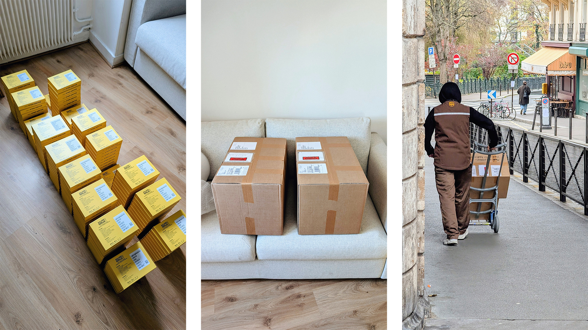
The first batch of units covering all pre-orders has just shipped, and it comes with a whole mix of emotions. It’s a bit strange to reach the end of something I’ve worked on (on and off) for eight years; it leaves a small empty space. But I’m also proud of having pushed this idea all the way into an actual product, grateful to the people who supported me along the way, and excited to finally see these in the wild. It’s the end of a long chapter, but it also leaves room for new projects.
Now, onto practical matters. In a few days, they will arrive at Mouser’s warehouse, and in no time they should be headed your way. So please ensure the shipping address you registered is still valid. If you encounter any issues, the Crowd Supply support page is the best place to go.
How I Made Sure Your Pen Actually Works
Now that we’ve covered that, let’s go over how I tried to make sure that each product shipped is fully functional. Before diving into the test bench, I want to talk briefly about how I approached quality.
Quality Starts at the Design Stage
For me, quality control doesn’t start at the end of the process. It starts way back at the design phase. There are various terms out there (design for manufacturability, for assembly, for testing) that all convey the same message: being thoughtful from the start so the later stages are smoother and more reliable.
Good manufacturers know what they can produce reliably, and often they will tell you this either directly or indirectly through their pricing. If you’re unsure, just have a conversation with them. For the Solder Ninja Pen, I took the time to compare quotes and sample multiple suppliers until I felt confident.
All of that lays the foundation, but design alone isn’t enough, you also need to see how the product behaves in the real world.
Testing in the Real World
Before hitting production, it’s always a good idea to actually use the product.
Use it yourself, because you’ll be more attuned to deviations from expected behavior. But also hand it to others, who bring their own expectations, hopefully representative of the target audience.
Testing outside in the wild is valuable because it gives you a preview of what might happen when you release your product outside the controlled conditions of your lab. For the Solder Ninja Pen, that’s how I discovered that the USB PD stack I had originally written didn’t handle certain edge cases gracefully.
And finally, testing for an extended period gives you insight into which components might fail sooner and whether the device is robust to the small accidents of life.
For the Solder Ninja Pen, I, and two other people, have been daily‑driving one for years in very different environments (company workshop, home lab, and on the go). Each of these perspectives catches different kinds of issues, and together they gave me confidence before moving into production.
Production Testing
So now we have a few hand‑assembled units working, and we have some level of confidence in the design and the suppliers. But we also know defects happen. Issues that don’t show up at small scale may become more visible when you ramp up production, so we still need to ensure that the units sent out into the world work.
The most functionally complicated part of the Solder Ninja Pen is its PCB. The rest is mostly mechanical parts that be inspected visually, but the PCB has many points that need to be verified. So much so that automation felt like an evidence: it saves time (a few seconds per unit adds up to hours at larger scale), and it avoids mistakes that a human might make.
So I decided to build a test bench. I sat down to think of all the possible ways a PCB could be defective and came up with a test for each. The bench runs these tests in one continuous sequence, and as a safeguard, it only prints the final label if everything passes.
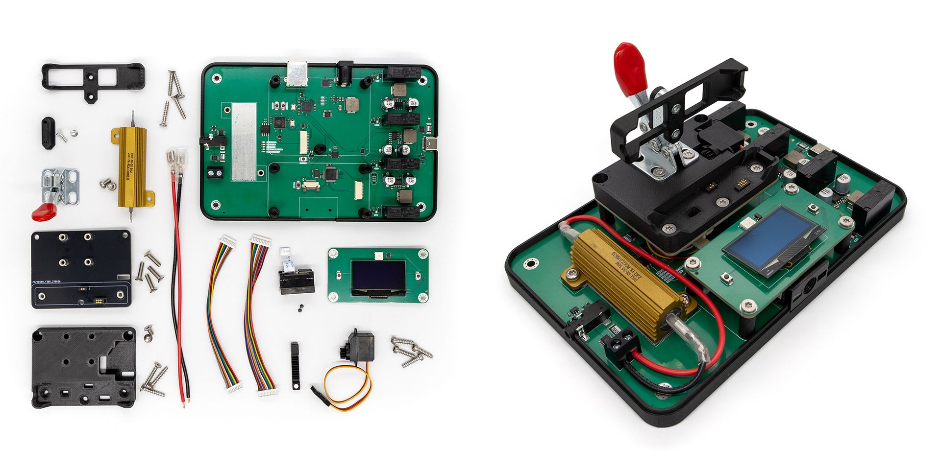
Before diving into its features, here’s a quick overview of its architecture. The test bench consists mainly of two stacked boards: an upper board that serves as a receptacle for the Pen PCB, aligning pogo pins with its test points and actuating a magnet for the Hall sensor, and a lower main board that handles all electronics. Powered from a 24 VDC input, the lower board includes an STM32 microcontroller, a tip‑emulation circuit, a 4‑to‑1 power‑supply multiplexer, a Raspberry Pi Debug Probe, and a USB hub that exposes all devices to the host computer through a good old USB Type‑B cable.
On the computer side, a program orchestrates the entire workflow: programming, testing, logging, printing labels, and saving reports over the network. The STM32 mostly acts as a pass‑through between the software and the hardware. I would have loved to make the whole thing self‑contained, but because of OpenOCD, the label printer, and the network access, I couldn’t really get by without an OS. For the upcoming batches, I might build a standalone version using a Raspberry Pi Compute Module and send it directly to PCBWay for testing.
Mechanically Interfacing With the Pen
None of the cool electronics matter unless the test bench can physically interface with the device under test.
This is in part handled by the upper board, which is tightly coupled to a 3D‑printed receptacle that guides the Pen PCB into place and aligns pogo pins with its test pads. The location of these pads has evolved over the revisions of the Pen, and might change again, so I decided to keep this entire interface block separate.
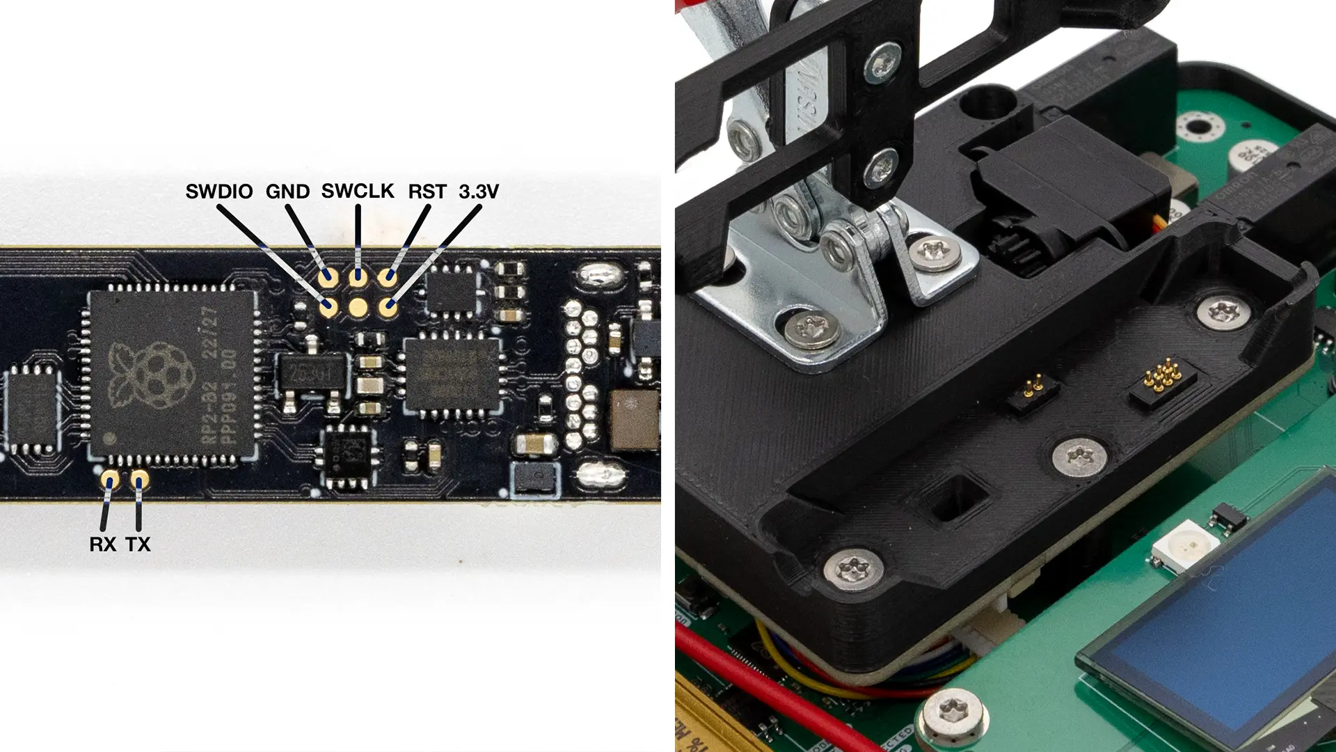
The Pen exposes several electrical test pads. The 3.3 V pad is used to verify the level of the logic rail. The SWD pads are used for programming, and the UART pads for reading logs during the test sequence. Since Raspberry Pi has published the schematics and firmware for their Debug Probe, I integrated that design directly into the bench. It appears as a regular USB device through the onboard hub and allows the software to program the RP2040 and collect UART logs over the same connection.
These pads don’t cover everything, though. Some features must be verified through their actual connectors. The Pen must still be tested through its USB‑C port, because pad‑only testing doesn’t confirm that the connector itself works. The same applies to the 3.5 mm jack for the tip. Manually plugging two cables isn’t ideal, but it guarantees that both connectors were soldered correctly.
There is also a Hall‑effect sensor used to detect whether the Pen is placed in a stand. The 3D‑printed block includes a mount for a small actuator that moves a real magnet near the sensor. The mechanism itself is described later, but keeping it on the interface module follows the same principle: everything that physically interacts with the Pen stays in this replaceable upper section.
Power Negotiation
The Solder Ninja Pen is designed to work with a wide variety of USB power sources, from simple 5 V chargers to more complex USB Power Delivery supplies. Even though PD is getting more common, verifying that the Pen behaves correctly with different standards remains important.
I wanted something more practical than repeatedly plugging and unplugging the Pen into a collection of off‑the‑shelf chargers, so here come relays!
On the right side of the bench, and thanks to charging‑controller ICs from Injoinic, I recreated the different power supplies that need to be tested. A set of relays switches the power path while signal multiplexers route the correct combinations of D+, D‑, and CC lines. This allows the bench to present itself as one type of charger, then switch to another in a fraction of a second, all while the software monitors how the Pen negotiates power.
Emulating the Tip
A Weller RT tip can be modeled as a combination of a thermocouple and a resistive heating element.
A thermocouple uses the Seebeck effect to generate a very small voltage difference depending on temperature. On the Pen, this voltage is measured by a MAX31855 analog front end. By chaining a precision DAC, a voltage divider, and an op‑amp in follower configuration, we can recreate this small‑signal. This allows us to emulate different temperatures and ensure that the Pen reads them within the expected range.
To emulate the resistive element, I used a hefty 2.1 Ω power resistor. It absorbs the power sent by the iron when attempting to heat, and an INA226 measures the power flowing into the resistor. By comparing that with the power drawn from the USB port, I can ensure that the efficiency remains within the acceptable range.
Magnet Testing
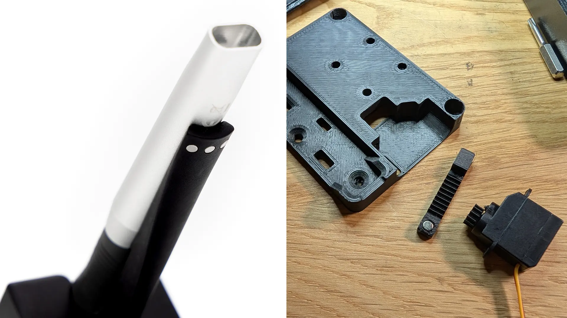
The Pen includes a Hall‑effect sensor to detect when it is placed in a stand. The first idea I explored was recreating the magnetic field of a stand using a hand-wound air-core inductor. That experiment ended with burnt fingertips and no measurable magnetic field, so I went with a simpler and far more reliable approach: actuating a real magnet. A tiny servo motor drives a surprisingly well-3D-printed pinion-and-rack mechanism embedded in the receptacle, moving the magnet near the sensor at the right moment in the test sequence.
Automated Labeling
This is a good example of how seemingly simple tasks can turn into multi-day adventures.
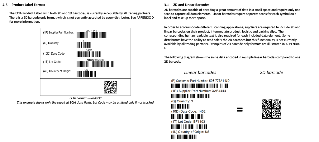
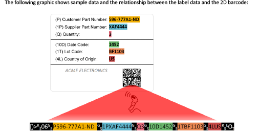
Have you ever noticed that parts you receive from major electronics distributors all have similar barcode-filled labels? That’s because the electronics industry has agreed on a 44-page long document for product and shipment identification. While Crowd Supply doesn’t require adopting the entire document, I still took it on as an exercice to do things properly. Below is an example of a product label described by the ECIA specification. Each data field appears both as human-readable text and as a 1D barcode, and all fields are summarized in a final 2D barcode.
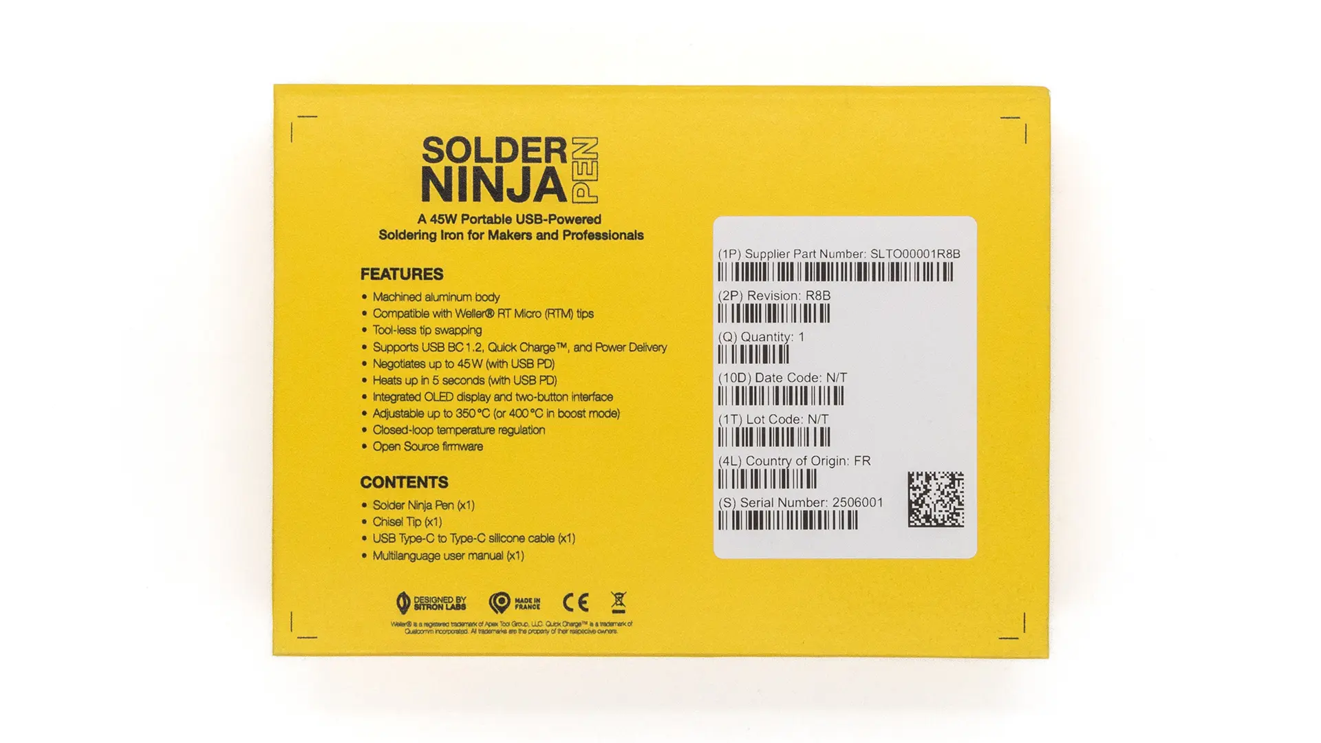
As mentioned in the previous update, I want each Solder Ninja Pen to be traceable with a serial number, and fortunately, the specification includes guidance on how serial numbers should appear on labels.
So at this point, I knew I needed to programmatically generate and print a label. Great, because I have some experience with that. I love Dymo (at least I used to before they switched to forcing DRM-enabled label rolls). They provide a horrible user-interface, but thankfully, they provide a localhost web API. The documentation for some of its features is almost non-existent, but the API is powerful: you can design a label template in the Dymo software, then replace specific fields programmatically before printing. It even generates 1D and 2D barcodes automatically.
Cool. Except that’s where I almost lost my sanity. Remember the 2D barcode that should summarize all the data fields of the label? It does include non-printable ASCII control characters as delimiters. And while the Dymo desktop software handles this without complaint, but the web API absolutely refuses to deal with them.
It took days to understand the problem, and a few more to find a workaround. In the end, I used the ZXing-CPP library to generate the 2D barcode as an image, base64-encode it, and embed it in the label template. Here’s the end result:
Closing Words
You can see the whole test bench in action in the video below. It takes less than a minute to test each Pen, how cool is that?!
With only a 4% failure rate, I’m quite happy with this first batch. The units that didn’t pass have been set aside and will be investigated to understand if improvements can be made to reduce the failure rate in future batches. When possible, they’ll be manually reworked and eventually resold as refurbished, so nothing goes to waste.
This is the first manufactured product I’ve produced at this scale on my own. I did my best to stack the odds in our favor, and I feel confident about this first batch. But the final part of a good quality process is listening to feedback. So good or bad, I’m eager to hear your stories. A great place to share them is the Crowd Supply Field Reports, or you can join our community on the Discord server.